Quantcast
Channel: EHSQL(Environment-Energy ,Health,Safety, Security and Social Ac. ,Quality-Lab) Technical services
Viewing all 8077 articles
Browse latest View live

IN ADVANCE VERY HAPPY BIRTH DAY TO NAGARJUNA GROUP CHAIRMAN Shri K.S.Raju SIR

$
0
0

The Nagarjuna Group under the stewardship and guidance of K S Raju is in the process of emerging as an enterprise based on values and commitment to the society at large. Shri K.S.Raju, fondly known as ‘KS’ by his peers and associates, was born at Nidadavole, West Godavari District, AP. He completed his Mechanical Engineering from University of Mysore in 1973, and embarked on the project which his father and he had initiated together - Nagarjuna Steels Limited. This project gave further impetus to development of industry in the state of Andhra Pradesh.
Highslide JS
Group Chairman K.S.Raju’s ability to initiate new projects proved to be a vital tool for success. He provided successful business leadership for the start up, before being called on to take the Group’s most critical role in its history - that of the leadership for the Group’s fertilizer project during its most challenging phase. He encouraged the Group’s foray into core sectors and structuring of businesses to meet the customer’s needs.
Apart from promoting business, K S Raju has always been proactive in  supporting community development activities in areas of environment, health, education and income generation to community asset creation. He has been closely associated with the World Business Academy and State of the World Forum. In association with these forums and with ILO, the Group initiated the K V K Raju International Leadership Academy, which works towards enabling managers become value based leaders.
K S Raju has served on the Boards of Administrative Staff College of India, Hyderabad, Indian Institute of Management, Bangalore, Court of Governors-University of Hyderabad and has also served as the Chairman of National Institute of Technical Teachers Training and Research, Chennai. He is one of the Founder Trustees of Naandi Foundation, Hyderabad.


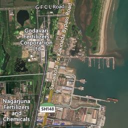
Kakinada Satellite NFCL AREAL VIEW 70 % COVERED BY GREEN BELT

$
0
0


© 2013 Nokia© 2012 DigitalGlobe© 2013 Microsoft Corporation

ELECTRIC SHOCK SAFETY ARTICLE -ANNUAL TURN AROUND

History of Radiography

$
0
0
History of Radiography
X-rays were discovered in 1895 by Wilhelm Conrad Roentgen (1845-1923) who was a Professor at Wuerzburg University in Germany. Working with a cathode-ray tube in his laboratory, Roentgen observed a fluorescent glow of crystals on a table near his tube. The tube that Roentgen was working with consisted of a glass envelope (bulb) with positive and negative electrodes encapsulated in it. The air in the tube was evacuated, and when a high voltage was applied, the tube produced a fluorescent glow. Roentgen shielded the tube with heavy black paper, and discovered a green colored fluorescent light generated by a material located a few feet away from the tube.
He concluded that a new type of ray was being emitted from the tube. This ray was capable of passing through the heavy paper covering and exciting the phosphorescent materials in the room. He found that the new ray could pass through most substances casting shadows of solid objects. Roentgen also discovered that the ray could pass through the tissue of humans, but not bones and metal objects. One of Roentgen's first experiments late in 1895 was a film of the hand of his wife, Bertha. It is interesting that the first use of X-rays were for an industrial (not medical) application, as Roentgen produced a radiograph of a set of weights in a box to show his colleagues.

Roentgen's discovery was a scientific bombshell, and was received with extraordinary interest by both scientist and laymen. Scientists everywhere could duplicate his experiment because the cathode tube was very well known during this period. Many scientists dropped other lines of research to pursue the mysterious rays. Newspapers and magazines of the day provided the public with numerous stories, some true, others fanciful, about the properties of the newly discovered rays.
Public fancy was caught by this invisible ray with the ability to pass through solid matter, and, in conjunction with a photographic plate, provide a picture of bones and interior body parts. Scientific fancy was captured by the demonstration of a wavelength shorter than light. This generated new possibilities in physics, and for investigating the structure of matter. Much enthusiasm was generated about potential applications of rays as an aid in medicine and surgery. Within a month after the announcement of the discovery, several medical radiographs had been made in Europe and the United States, which were used by surgeons to guide them in their work. In June 1896, only 6 months after Roentgen announced his discovery, X-rays were being used by battlefield physicians to locate bullets in wounded soldiers.

Prior to 1912, X-rays were used little outside the realms of medicine and dentistry, though some X-ray pictures of metals were produced. The reason that X-rays were not used in industrial application before this date was because the X-ray tubes (the source of the X-rays) broke down under the voltages required to produce rays of satisfactory penetrating power for industrial purposes. However, that changed in 1913 when the high vacuum X-ray tubes designed by Coolidge became available. The high vacuum tubes were an intense and reliable X-ray source, operating at energies up to 100,000 volts.
In 1922, industrial radiography took another step forward with the advent of the 200,000-volt X-ray tube that allowed radiographs of thick steel parts to be produced in a reasonable amount of time. In 1931, General Electric Company developed 1,000,000 volt X-ray generators, providing an effective tool for industrial radiography. That same year, the American Society of Mechanical Engineers (ASME) permitted X-ray approval of fusion welded pressure vessels that further opened the door to industrial acceptance and use.
A Second Source of Radiation
Shortly after the discovery of X-rays, another form of penetrating rays was discovered. In 1896, French scientist Henri Becquerel discovered natural radioactivity. Many scientists of the period were working with cathode rays, and other scientists were gathering evidence on the theory that the atom could be subdivided. Some of the new research showed that certain types of atoms disintegrate by themselves. It was Henri Becquerel who discovered this phenomenon while investigating the properties of fluorescent minerals. Becquerel was researching the principles of fluorescence, wherein certain minerals glow (fluoresce) when exposed to sunlight. He utilized photographic plates to record this fluorescence.
One of the minerals Becquerel worked with was a uranium compound. On a day when it was too cloudy to expose his samples to direct sunlight, Becquerel stored some of the compound in a drawer with his photographic plates. Later when he developed these plates, he discovered that they were fogged (exhibited exposure to light). Becquerel questioned what would have caused this fogging. He knew he had wrapped the plates tightly before using them, so the fogging was not due to stray light. In addition, he noticed that only the plates that were in the drawer with the uranium compound were fogged. Becquerel concluded that the uranium compound gave off a type of radiation that could penetrate heavy paper and expose photographic film. Becquerel continued to test samples of uranium compounds and determined that the source of radiation was the element uranium. Bacquerel's discovery was, unlike that of the X-rays, virtually unnoticed by laymen and scientists alike. Relatively few scientists were interested in Becquerel's findings. It was not until the discovery of radium by the Curies two years later that interest in radioactivity became widespread.
While working in France at the time of Becquerel's discovery, Polish scientist Marie Curie became very interested in his work. She suspected that a uranium ore known as pitchblende contained other radioactive elements. Marie and her husband, French scientist Pierre Curie, started looking for these other elements. In 1898, the Curies discovered another radioactive element in pitchblende, and named it 'polonium' in honor of Marie Curie's native homeland. Later that year, the Curies discovered another radioactive element which they named radium, or shining element. Both polonium and radium were more radioactive than uranium. Since these discoveries, many other radioactive elements have been discovered or produced.
Radium became the initial industrial gamma ray source. The material allowed castings up to 10 to 12 inches thick to be radiographed. During World War II, industrial radiography grew tremendously as part of the Navy's shipbuilding program. In 1946, man-made gamma ray sources such as cobalt and iridium became available. These new sources were far stronger than radium and were much less expensive. The manmade sources rapidly replaced radium, and use of gamma rays grew quickly in industrial radiography.
Health Concerns
The science of radiation protection, or "health physics" as it is more properly called, grew out of the parallel discoveries of X-rays and radioactivity in the closing years of the 19th century. Experimenters, physicians, laymen, and physicists alike set up X-ray generating apparatuses and proceeded about their labors with a lack of concern regarding potential dangers. Such a lack of concern is quite understandable, for there was nothing in previous experience to suggest that X-rays would in any way be hazardous. Indeed, the opposite was the case, for who would suspect that a ray similar to light but unseen, unfelt, or otherwise undetectable by the senses would be damaging to a person? More likely, or so it seemed to some, X-rays could be beneficial for the body.
Inevitably, the widespread and unrestrained use of X-rays led to serious injuries. Often injuries were not attributed to X-ray exposure, in part because of the slow onset of symptoms, and because there was simply no reason to suspect X-rays as the cause. Some early experimenters did tie X-ray exposure and skin burns together. The first warning of possible adverse effects of X-rays came from Thomas Edison, William J. Morton, and Nikola Tesla who each reported eye irritations from experimentation with X-rays and fluorescent substances.
Today, it can be said that radiation ranks among the most thoroughly investigated causes of disease. Although much still remains to be learned, more is known about the mechanisms of radiation damage on the molecular, cellular, and organ system than is known for most other health stressing agents. Indeed, it is precisely this vast accumulation of quantitative dose-response data that enables health physicists to specify radiation levels so that medical, scientific, and industrial uses of radiation may continue at levels of risk no greater than, and frequently less than, the levels of risk associated with any other technology.
X-rays and Gamma rays are electromagnetic radiation of exactly the same nature as light, but of much shorter wavelength. Wavelength of visible light is on the order of 6000 angstroms while the wavelength of x-rays is in the range of one angstrom and that of gamma rays is 0.0001 angstrom. This very short wavelength is what gives x-rays and gamma rays their power to penetrate materials that light cannot. These electromagnetic waves are of a high energy level and can break chemical bonds in materials they penetrate. If the irradiated matter is living tissue, the breaking of chemical bonds may result in altered structure or a change in the function of cells. Early exposures to radiation resulted in the loss of limbs and even lives. Men and women researchers collected and documented information on the interaction of radiation and the human body. This early information helped science understand how electromagnetic radiation interacts with living tissue. Unfortunately, much of this information was collected at great personal

Controlling Radiation Exposure

$
0
0
Controlling Radiation Exposure
When working with radiation, there is a concern for two types of exposure: acute and chronic. An acute exposure is a single accidental exposure to a high dose of radiation during a short period of time. An acute exposure has the potential for producing both nonstochastic and stochastic effects. Chronic exposure, which is also sometimes called "continuous exposure," is long-term, low level overexposure. Chronic exposure may result in stochastic health effects and is likely to be the result of improper or inadequate protective measures.
The three basic ways of controlling exposure to harmful radiation are: 1) limiting the time spent near a source of radiation, 2) increasing the distance away from the source, 3) and using shielding to stop or reduce the level of radiation.
Time
The radiation dose is directly proportional to the time spent in the radiation. Therefore, a person should not stay near a source of radiation any longer than necessary. If a survey meter reads 4 mR/h at a particular location, a total dose of 4mr will be received if a person remains at that location for one hour. In a two hour span of time, a dose of 8 mR would be received. The following equation can be used to make a simple calculation to determine the dose that will be or has been received in a radiation area.
Dose = Dose Rate x Time
When using a gamma camera, it is important to get the source from the shielded camera to the collimator as quickly as possible to limit the time of exposure to the unshielded source. Devices that shield radiation in some directions but allow it pass in one or more other directions are known as collimators. This is illustrated in the images at the bottom of this page.
Distance
Increasing distance from the source of radiation will reduce the amount of radiation received. As radiation travels from the source, it spreads out becoming less intense. This is analogous to standing near a fire. The closer a person stands to the fire, the more intense the heat feels from the fire. This phenomenon can be expressed by an equation known as the inverse square law, which states that as the radiation travels out from the source, the dosage decreases inversely with the square of the distance.
Inverse Square Law:    I1/ I2 = D22/ D12
(
Shielding
The third way to reduce exposure to radiation is to place something between the radiographer and the source of radiation. In general, the more dense the material the more shielding it will provide. The most effective shielding is provided by depleted uranium metal. It is used primarily in gamma ray cameras like the one shown below. The circle of dark material in the plastic see-through camera (below right) would actually be a sphere of depleted uranium in a real gamma ray camera. Depleted uranium and other heavy metals, like tungsten, are very effective in shielding radiation because their tightly packed atoms make it hard for radiation to move through the material without interacting with the atoms. Lead and concrete are the most commonly used radiation shielding materials primarily because they are easy to work with and are readily available materials. Concrete is commonly used in the construction of radiation vaults. Some vaults will also be lined with lead sheeting to help reduce the radiation to acceptable levels on the outside.
 

Health effects from exposure to ionizing radiation

$
0
0
Biological Effects
The occurrence of particular health effects from exposure to ionizing radiation is a complicated function of numerous factors including:
  • Type of radiation involved. All kinds of ionizing radiation can produce health effects. The main difference in the ability of alpha and beta particles and Gamma and X-rays to cause health effects is the amount of energy they have. Their energy determines how far they can penetrate into tissue and how much energy they are able to transmit directly or indirectly to tissues.  
  • Size of dose received. The higher the dose of radiation received, the higher the likelihood of health effects.
  • Rate the dose is received. Tissue can receive larger dosages over a period of time. If the dosage occurs over a number of days or weeks, the results are often not as serious if a similar dose was received in a matter of minutes.
  • Part of the body exposed. Extremities such as the hands or feet are able to receive a greater amount of radiation with less resulting damage than blood forming organs housed in the torso. 
  • The age of the individual. As a person ages, cell division slows and the body is less sensitive to the effects of ionizing radiation. Once cell division has slowed, the effects of radiation are somewhat less damaging than when cells were rapidly dividing.
  • Biological differences. Some individuals are more sensitive to the effects of radiation than others. Studies have not been able to conclusively determine the differences.
  • Stochastic Effects
    Stochastic effects are those that occur by chance and consist primarily of cancer and genetic effects. Stochastic effects often show up years after exposure. As the dose to an individual increases, the probability that cancer or a genetic effect will occur also increases. However, at no time, even for high doses, is it certain that cancer or genetic damage will result. Similarly, for stochastic effects, there is no threshold dose below which it is relatively certain that an adverse effect cannot occur. In addition, because stochastic effects can occur in individuals that have not been exposed to radiation above background levels, it can never be determined for certain that an occurrence of cancer or genetic damage was due to a specific exposure.
    While it cannot be determined conclusively, it often possible to estimate the probability that radiation exposure will cause a stochastic effect. As mentioned previously, it is estimated that the probability of having a cancer in the US rises from 20% for non radiation workers to 21% for persons who work regularly with radiation. The probability for genetic defects is even less likely to increase for workers exposed to radiation. Studies conducted on Japanese atomic bomb survivors who were exposed to large doses of radiation found no more genetic defects than what would normally occur.
    Radiation-induced hereditary effects have not been observed in human populations, yet they have been demonstrated in animals. If the germ cells that are present in the ovaries and testes and are responsible for reproduction were modified by radiation, hereditary effects could occur in the progeny of the individual. Exposure of the embryo or fetus to ionizing radiation could increase the risk of leukemia in infants and, during certain periods in early pregnancy, may lead to mental retardation and congenital malformations if the amount of radiation is sufficiently high.
     
    Cancer
    Cancer is any malignant growth or tumor caused by abnormal and uncontrolled cell division.  Cancer may spread to other parts of the body through the lymphatic system or the blood stream. The carcinogenic effects of doses of 100 rads (1 Gy) or more of gamma radiation delivered at high dose rates are well documented, consistent and definitive.
    Although any organ or tissue may develop a tumor after overexposure to radiation, certain organs and tissues seem to be more sensitive in this respect than others. Radiation-induced cancer is observed most frequently in the hemopoietic system, in the thyroid, in the bone, and in the skin.  In all these cases, the tumor induction time in man is relatively long - on the order of 5 to 20 years after exposure.
    Carcinoma of the skin was the first type of malignancy that was associated with exposure to x-rays. Early x-ray workers, including physicists and physicians, had a much higher incidence of skin cancer than could be expected from random occurrences of this disease. Well over 100 cases of radiation induced skin cancer are documented in the literature. As early as 1900, a physician who had been using x-rays in his practice described the irritating effects of x-rays. He recorded that erythema and itching progressed to hyper-pigmentation, ulceration, neoplasia, and finally death from metastatic carcinoma. The entire disease process spanned a period of 9 years. Cancer of the fingers was an occupational disease common among dentists before the carcinogenic properties of x-rays were well understood. Dentists would hold the dental x-ray film in the mouths of patients while x-raying their teeth.
    Leukemia
    Leukemia is a cancer of the early blood-forming cells. Usually, the leukemia is a cancer of the white blood cells, but leukemia can involve other blood cell types as well. Leukemia starts in the bone marrow and then spreads to the blood. From there it can go to the lymph nodes, spleen, liver, central nervous system (the brain and spinal cord), testes (testicles), or other organs. Leukemia is among the most likely forms of malignancy resulting from overexposure to total body radiation. Chronic lymphocytic leukemia does not appear to be related to radiation exposure.
    Radiologists and other physicians who used x-rays in their practice before strict health physics practices were common showed a significantly higher rate of leukemia than did their colleagues who did not use radiation. Among American radiologists, the doses associated with the increased rate of leukemia were on the order of 100 rads (1 Gy) per year. With the increased practice of health physics, the difference in leukemia rate between radiologists and other physicians has been continually decreasing.
    Among the survivors of the nuclear bombings of Japan, there was a significantly greater incidence of leukemia among those who had been within 1500 meters of the hypocenter than among those who had been more than 1500 meters from ground zero at the time of the bombing. An increase in leukemia among the survivors was first seen about three years after the bombings, and the leukemia rate continued to increase until it peaked about four years later. Since this time, the rate has been steadily decreasing.
    The questions regarding the leukemogenicity of low radiation doses and of the existence of a non-zero threshold dose for leukemia induction remain unanswered, and are the subject of controversy. On the basis of a few limited studies, it was inferred that as little as 1-5 rads (10-50 mGy) of x-rays could lead to leukemia. Other studies imply that a threshold dose for radiogenic leukemia is significantly higher. However, it is reasonable to infer that low level radiation at doses associated with most diagnostic x-ray procedures, with occupational exposure within the recommended limits, and with natural radiation is a very weak leukemogen, and that the attributive risk of leukemia from low level radiation is probably very small.
    Genetic Effects
    Genetic information necessary for the production and functioning of a new organism is contained in the chromosomes of the germ cells - the sperm and the ovum. The normal human somatic cell contains 46 of these chromosomes; mature sperm and ovum each carry 23 chromosomes. When an ovum is fertilized by a sperm, the resulting cell, called a zygote, contains a full complement of 46 chromosomes. During the 9-month gestation period, the fertilized egg, by successive cellular division and differentiation, develops into a new individual. In the course of the cellular divisions, the chromosomes are exactly duplicated, so that cells in the body contain the same genetic information. The units of information in the chromosomes are called genes. Each gene is an enormously complex macromolecule called deoxyribonucleic acid (DNA), in which the genetic information is coded according to the sequence of certain molecular and sub-assemblies called bases. The DNA molecule consists of two long chains in a spiral double helix. The two long intertwined strands are held together by the bases, which form cross-links between the long strands in the same manner as the treads in a step-ladder.
    The genetic information can be altered by many different chemical and physical agents called mutagens, which disrupt the sequence of bases in a DNA molecule. If this information content of a somatic cell is scrambled, then its descendants may show some sort of an abnormality. If the information that is jumbled is in a germ cell that subsequently is fertilized, then the new individual may carry a genetic defect, or a mutation. Such a mutation is often called a point mutation, since it results from damage to one point on a gene. Most geneticists believe that the majority of such mutations in man are undesirable or harmful.
    In addition to point mutations, genetic damage can arise through chromosomal aberrations. Certain chemical and physical agents can cause chromosomes to break. In most of these breaks, the fragments reunite, and the only result may be a point mutation at the site of the original break. In a small fraction of breaks, however, the broken pieces do not reunite. When this happens, one of the broken fragments may be lost when the cell divides, and the daughter cell does not receive the genetic information contained in the lost fragment. The other possibility following chromosomal breakage, especially if two or more chromosomes are broken, is the interchange of the fragments among the broken chromosomes, and the production of aberrant chromosomes. Cells with such aberrant chromosomes usually have impaired reproductive capacity as well as other abnormalities.
    Studies suggest that the existence of a threshold dose for the genetic effects of radiation is unlikely. However, they also show that the genetic effects of radiation are inversely dependent on dose rate over the range of 800 mrad/min (8 mGy/min) to 90 rads/min (0.9 Gy/min). The dose rate dependence clearly implies a repair mechanism that is overwhelmed at the high dose rate. Geneticists estimate that there are 320 chances per million of a "spontaneous" mutation in a dominant gene trait of a person. The radiation dose that would eventually lead to a doubling of the mutation rate is estimated to be in the range of 50-250 rads (0.5-2.5 Gy).
    Cataracts
    A cataract is a clouding of the normally clear lens of the eye. A much higher incidence of cataracts was reported among physicists in cyclotron laboratories whose eyes had been exposed intermittently for long periods of time to relatively low radiation fields, as well as among atomic bomb survivors whose eyes had been exposed to a single high radiation dose. This shows that both chronic and acute overexposure of the eyes can lead to cataracts. Radiation may injure the cornea, conjunctiva, iris, and the lens of the eye. In the case of the lens, the principal site of damage is the proliferating cells of the anterior epithelium. This results in abnormal lens fibers, which eventually disintegrate to form an opaque area, or cataract, that prevents light from reaching the retina.
    The cataractogenic dose to the lens is on the order of 500 rad of beta or gamma radiation. No radiogenic cataracts resulting from occupational exposure to x-rays have been reported. From patients who suffered irradiation of the eye in the course of x-ray therapy and developed cataracts as a consequence, the cataractogenic threshold is estimated at about 200 rad. In cases either of occupationally or therapeutically induced radiation cataracts, a long latent period, on the order of several years, usually elapsed between the exposure and the appearance of the lens opacity. The cataractogenic dose has been found, in laboratory experiments with animals, to be a function of age; young animals are more sensitive than old animals.
    Nonstochastic (Acute) Effects
    Unlike stochastic effects, nonstochastic effects are characterized by a threshold dose below which they do not occur. In other words, nonstochastic effects have a clear relationship between the exposure and the effect. In addition, the magnitude of the effect is directly proportional to the size of the dose. Nonstochastic effects typically result when very large dosages of radiation are received in a short amount of time. These effects will often be evident within hours or days. Examples of nonstochastic effects include erythema (skin reddening), skin and tissue burns, cataract formation, sterility, radiation sickness and death. Each of these effects differs from the others in that both its threshold dose and the time over which the dose was received cause the effect (i.e. acute vs. chronic exposure).
    There are a number of cases of radiation burns occurring to the hands or fingers. These cases occurred when a radiographer touched or came in close contact with a high intensity radiation emitter. Intensity on the surface of an 85 curie Ir-192 source capsule is approximately 1,768 R/s. Contact with the source for two seconds would expose the hand of an individual to 3,536 rems, and this does not consider any additional whole body dosage received when approaching the source.
    More on Specific Nonstochastic Effects
    Hemopoietic Syndrome
    The hemopoietic syndrome encompasses the medical conditions that affect the blood. Hemopoietic syndrome conditions appear after a gamma dose of about 200 rads (2 Gy). This disease is characterized by depression or ablation of the bone marrow, and the physiological consequences of this damage. The onset of the disease is rather sudden, and is heralded by nausea and vomiting within several hours after the overexposure occurred. Malaise and fatigue are felt by the victim, but the degree of malaise does not seem to be correlated with the size of the dose. Loss of hair (epilation), which is almost always seen, appears between the second and third week after the exposure. Death may occur within one to two months after exposure. The chief effects to be noted, of course, are in the bone marrow and in the blood. Marrow depression is seen at 200 rads and at about 400 to 600 rads (4 to 6 Gy) complete ablation of the marrow occurs. In this case, however, spontaneous regrowth of the marrow is possible if the victim survives the physiological effects of the denuding of the marrow. An exposure of about 700 rads (7 Gy) or greater leads to irreversible ablation of the bone marrow.
    Gastrointestinal Syndrome
    The gastrointestinal syndrome encompasses the medical conditions that affect the stomach and the intestines. This medical condition follows a total body gamma dose of about 1000 rads (10 Gy) or greater, and is a consequence of the desquamation of the intestinal epithelium. All the signs and symptoms of hemopoietic syndrome are seen, with the addition of severe nausea, vomiting, and diarrhea which begin very soon after exposure. Death within one to two weeks after exposure is the most likely outcome.
    Central Nervous System
    A total body gamma dose in excess of about 2000 rads (20 Gy) damages the central nervous system, as well as all the other organ systems in the body. Unconsciousness follows within minutes after exposure and death can result in a matter of hours to several days. The rapidity of the onset of unconsciousness is directly related to the dose received. In one instance in which a 200 msec burst of mixed neutrons and gamma rays delivered a mean total body dose of about 4400 rads (44 Gy), the victim was ataxic and disoriented within 30 seconds. In 10 minutes, he was unconscious and in shock. Vigorous symptomatic treatment kept the patient alive for 34 hours after the accident.
    Other Acute Effects
    Several other immediate effects of acute overexposure should be noted. Because of its physical location, the skin is subject to more radiation exposure, especially in the case of low energy x-rays and beta rays, than most other tissues. An exposure of about 300 R (77 mC/kg) of low energy (in the diagnostic range) x-rays results in erythema. Higher doses may cause changes in pigmentation, loss of hair, blistering, cell death, and ulceration. Radiation dermatitis of the hands and face was a relatively common occupational disease among radiologists who practiced during the early years of the twentieth century.
    The reproductive organs are particularly radiosensitive. A single dose of only 30 rads (300 mGy) to the testes results in temporary sterility among men. For women, a 300 rad (3 Gy) dose to the ovaries produces temporary sterility. Higher doses increase the period of temporary sterility. In women, temporary sterility is evidenced by a cessation of menstruation for a period of one month or more, depending on the dose. Irregularities in the menstrual cycle, which suggest functional changes in the reproductive organs, may result from local irradiation of the ovaries with doses smaller than that required for temporary sterilization.
    The eyes too, are relatively radiosensitive. A local dose of several hundred rads can result in acute conjunctivitis.

Appeal from Hon'ble Chief Minister Uttarakhand

PM's Appeal

$
0
0
My Fellow Citizens,
You are all aware that there has been extensive devastation due to cloud burst and floods in the State of Uttarakhand.  A large number of persons have died and property worth crores of rupees has been damaged. The Union Government is extending all cooperation and assistance to the State Government in rescue and relief operations.
2. At this moment, affected people need our help to tide over the calamity that has fallen upon them, to survive and to rebuild their lives. I request all citizens of India to stand with our distressed fellow countrymen, and actively participate in the national effort to support them at this difficult time.
3. I appeal to all citizens to donate generously to the Prime Minister’s National Relief Fund [PMNRF].
Payment may be made by cheque or draft in the name of the “Prime Minister’s National Relief Fund” and sent to the Prime Minister’s Office, South Block, New Delhi 110011. As per directions on the subject the nationalized banks are not to charge any commission on preparation of drafts favouring the PMNRF. Online contributions can also be made through the website of Prime Minister’s Office i.e. www.pmindia.nic.in.
Contributions can also be made directly in the account of Prime Minister’s National Relief Fund at the branches of the following banks: Allahabad Bank, Andhra Bank, Axis Bank, Bank of Baroda, Bank of India, Bank of Maharashtra, Canara Bank, Central Bank of India, Citi Bank, Corporation Bank, Dena Bank, HDFC Bank, ICICI Bank, IDBI Bank Limited, Indian Bank, Indian Overseas Bank, Kotak Mahindra Bank, Oriental Bank of Commerce, Punjab and Sind Bank, Punjab National Bank, Standard Chartered Bank, State Bank of India, Syndicate Bank, UCO Bank, Union Bank of India, United Bank of India, Vijaya Bank, and Yes Bank Limited.
Contributions can also be sent through Money Order with no commission chargeable. Contributions to the PMNRF have been notified for 100% deduction from taxable income under section 80(G) of the Income Tax Act.


PROF RAM GOPAL YADAV

Railways to carry relief material for Uttarakhand free of cost

$
0
0
Railways to carry relief material for Uttarakhand free of cost
The Ministry of Railways has decided that relief material, viz. food, medicines, clothes, building materials, utensils etc, will be carried to Uttarakhand free of cost by coaching trains, from any station in India, for a period of 15 days, i.e. from 25.06.2013 to 09.07.2013.

The relief material will be consigned to the District Magistrate of the concerned district on production of a certificate from the consignor that the consignment is a gift in kind or has been purchased with the funds donated by public for flood victims and has not been paid for by the Government or any of its agencies.

No claim for any loss or damage to consignment carried under this arrangement will be entertained unless it is clearly proved that the loss or damage took place due to willful negligence on the part of the Railways.


***


AKS/SK
(Release ID :96735)

UPDATE ON RESCUE AND RELIEF OPERATIONS IN UTTRAKHAND

List Rescued Person

$
0
0

Cooling Water Systems – Audit and Future Trends

$
0
0

Cooling Water Systems – Audit and Future Trends

The major problems associated with any cooling water system are corrosion, scaling, fouling and microbial growth.
Cooling Water Systems - Problems
The principal objective of a good cooling water treatment programme is to prevent corrosion to extend equipment life, inhibit scale and deposit build up to maintain heat transfer across the exchangers/condensers and control the growth of micro-organisms which can both-corrode and foul the system. The objective is also to permit extended operation of the plant without necessitating any shut down due to water related problems. In today’s competitive scenario it is also necessary to continuously provide value addition and reduce the total cost of operation while fulfilling the above mentioned objectives, and it is here that many treatment programmes are found wanting.
On many occasions a water treatment vendor is selected based on the lowest cost. As with any industry, competition is also fierce in the water treatment segment and when the lowest quote is provided it is often only the basic requirements that are provided. The fine balance between cost and performance limits the flexibility of the treatment programme and operation, which is essential for value added programmes and services. Correct technical water treatment solution at the right price creates a WIN-WIN situation for both the plant and the water treatment company.
Value addition and reduction in the cost of operation can be realized when both work as true partners. After all the plant personnel know the plant best and the water treatment company knows their chemicals and programmes best. The two then have to harness their resources and work together to get the best out of any treatment programme. This approach brings in an atmosphere of trust, and transparency automatically follows paving the way for ‘Ethical Proposals’ of value for money without shortchanging either the equipment or performance.
The critical step in value added services is to conduct an audit. This is not to be construed as a compliance audit but should be purely a fact finding procedure. Only when a closer look is taken can areas of improvement be identified. The audit exercise should be broad based and the process of achieving them multidimensional to cover all angles of operations to arrive at the right conclusions and implementation of best practices within the operational constraints. The aim should be to maximize the returns on the investment that the plant makes by selecting a water treatment company as their partner in water management. This is what we call the ‘IPO’ of a cooling water treatment audit – Intent, Procedure and Output.
The intent of any cooling water treatment audit is three fold:
    MEASURE THE EFFECTIVENESS
    IMPROVE UPON THE PRACTICES
    INSTITUTE AND STANDARDIZE IMPROVEMENTS
In order to carry out the audit the following procedure is suggested:
A. Review the current conditions and service standards
This is the starting point and forms the baseline data. Here, one can collect the following;
    • Details of the treatment programme currently used.
    • Overall treatment performance currently achieved and history.
    • History of critical equipment and parameters.
    • Critical process data relevant to water treatment.
    • Specific contaminants, if present.
B.Collect system information in depth
The system and operational details are then gathered along with the water flow chart. Storage and pretreatment data , stagnant zones, Cooling tower structural information, seasonal wind direction and nearby equipment that can alter or influence the water parameters are some areas that can often provide valuable inputs for overall improvement.
C. Gather records, data and statistics
The data for screening could include;
    • Daily log sheets at operating levels
    • Daily water analysis data
    • The water flow diagrams
    • Flow mapping data
    • Monitoring data and records
    • Data on microbial analysis
    • Data on corrosion rates measured
    • Exchanger monitoring data
    • Various sample and product analysis
    • Consumption of chemicals
    • Specific observations made by the people on site
    • Seasonal variations
D. Evaluate programme performance
The programme performance evaluation is generally based on:
a. Corrosion control
b. Microbial control
c. Scaling & deposition control
d. General water chemistry
e. Heat exchanger behavior pattern
f. Heat exchanger inspection reports
E. Conduct site interviews/special studies
A very important and integral part of any audit is site interviews with key operating people at all levels. While providing important feedback on the present condition and performance, these interviews go a long way in providing critical information on the concerns and needs of the plant and also highlight operational limitations, if any.
Special studies could be diagnostic or analytical to arm us with more information or reconfirm existing data that can be beneficially used.
F. Measure costs: Actual Vs. capability
This data will allow us to optimize the feed rates of various chemicals and fine tune their frequency of addition to bring in direct benefits to the plant. Variations in the regular maintenance level can be reduced and the chemicals can be maintained in a narrower band of operation to avoid wide fluctuations and overfeed of chemicals.
G. Overall review and presentation
Once all the information is collated a detailed study of the data is necessary to suggest any improvements with regard to the system, programme and/or services to bring in value addition and cost benefit which is the sole objective of such an audit. The findings and suggestions should then be logically presented to the key officials of the unit who can then assist in the implementations of the suggested improvements.
OUTPUT
The whole purpose of an audit is the Pay Off. Some the pay offs could be;
    • Optimisation of the treatment programme
    • Improvement of the treatment performance
    • Operation at higher stress conditions to save water
    • Use discharge of other areas that would normally drain to the effluent as make up
    • Effluent recycle
    • Removal of bottlenecks to improve plant load (productivity)
AUDIT – Summary and Check list:
As a summary, provided below is the audit check list in assisting a cooling water audit. This is a typical audit check list and depending on the system and the need it can be modified to suit individual requirement.
Audit Summary – Checklist
1Current Conditions and Service Review

a.Treatment programme details

b.General observations

c.Corrosion observations

d.Scaling observations

e.Fouling observations

f.Microbiology observations
2System Information

a.System details

b.Hx details

c.Plant location details
3Records, Data and Statistics

a.General observations & comments
4Programme Performance Evaluation

a.Corrosion control

b.Microbial control

c.Scale & deposit control

d.General water chemistry

e.Hx behavior pattern
5Site Interviews
6Special studies

a.Diagnostic

b.Microbial

c.Analytical
7Costs; Actual vs Design
8Overall Review & Recommendation

a.System

b.Programme

c.Service
AUDIT Findings: Examples
Example 1: A chemical plant in North India used river water for all their utilities. The river water was transported over 17kms and stored. The water was chlorinated in the plant battery limit before use. However SRB attack was still observed in the system and was particularly high in the transport pipelines. After detailed investigation it was found that a distillery existed upstream of the river from were the water was pumped to site and the waste water from the distillery was the cause of high microbial activity. Chlorination was started in the intake well in the river itself to get over the problem.
Example 2: Two plants located at a distance from each other produced the same product. They had identical technology and the plants were also identical in all respects. Both the plants had identical treatment programme. However one plant faced severe nitrifying bacteria problem and the other had severe sulfate reducing bacteria problem. Detailed audit helped in overcoming the problems at both sites. It was found that during certain periods the wind direction inoculated the cooling water systems with soil from the surrounding area.
One plant had an agricultural surrounding (Use of nitrogenous fertilizers) which brought nitrifying bacteria into the system. The other plant had many industries including sugar factories around it and that contributed towards SRB ingress into the system. The problems were addressed and resolved with specific microbial control regime.
Example 3: A unit in South-West India had three cooling towers at site. Similar programmes were applied in all the three cooling water systems. However it was found that while two systems yielded good treatment performance (CR 1-2 mpy), the corrosion rate in the third tower was always very high (8-12 mpy). This was initially baffling as the water chemistry and COC were identical. Infact the COC in the third tower was usually higher which should have reduced the corrosion potential when compared with the other towers. Initially it was thought that the sulfur dioxide from the surrounding stacks contributed to higher SRB leading to higher corrosion rate.
Specific biocide at increased frequency yielded only marginal benefit. After a detailed audit along with extensive lab and field studies at site it was found that the bulk return water temperature was very high (48 to 52 deg C) as compared to the other towers where it was normal. Initially the problem was solved by modifying the chemical treatment programme. Subsequently as a permanent measure an additional cell was constructed and attached to the system. After this the regular treatment programme as implemented in the other towers, provided similar good performance in the system.
Example 4: A chemical plant in Eastern India had a treatment programme that was yielding good treatment performance in all respects. However it was found that one particular high temperature condenser was becoming a bottleneck and it needed to be frequently cleaned. Due to high temperature the scales were predominantly calcium phosphate. After detailed studies and calculations and in partnership with the plant’s technical cell it was decided to convert the exchanger to two pass. This was a mechanical solution which solved the problem, as no deposit control agent would have provided any relief at those high temperatures.
Example 5: After a long good run, rapid deterioration was observed in the performance of a turbine condenser in a petrochemical plant. Further deterioration could result in a plant shutdown. The need of the hour was to quickly find the cause of the problem and rectify it. Initially it was suspected that scaling could be the problem which would necessitate on line cleaning, a tedious process. Observation of the other exchangers and the HTC data of critical exchangers did not show or indicate any scaling. It was then suspected that physical fouling could have reduced the water flow through the condenser as some physical fouling had been observed earlier during the turn around. Detailed flow studies were conducted with ultrasonic flow meters and it was observed that the water flow had considerably reduced. Armed with this data, it was decided to back-flush the condenser. Back-flushing solved the problem and vacuum and process side temperatures were restored. This averted a shutdown of the plant.
PART II
LATEST TRENDS:
Let us now take a look at some of the latest trends in cooling water treatment. This can be looked at from;
    • the chemical treatment side,
    • monitoring and automated dosing systems and
    • Operational aspects.
Chemical Treatment Programmes:
As mentioned earlier the main problems associated with any cooling water system are corrosion, scaling, fouling and microbial growth. The most commonly adopted programme today includes zinc and orthophosphate as the main corrosion inhibitors along with organophosphonates and polymers for scale and deposit control. Microbial control is achieved with the continuous use of an oxidizing biocide, commonly chlorine, along with a biodispersant, which are specific surfactants, for the removal of slime and organic contaminants. Once these biofilm are prevented from adhering to the exchanger tubes and kept in suspension and circulation in the cooling water, the oxidizing biocide can attack and kill these organisms thereby preventing the build up of slime in the system. Periodically non-oxidizing biocides are used to supplement the action of chlorine and biodispersant.
What are the latest and the future trends in each of these areas are worth taking a look at.
Corrosion Inhibition:
Cathodic and an Anodic Corrosion Inhibitor
It is well established that a synergistic combination of a cathodic and an anodic corrosion inhibitor provides the best corrosion protection. However there are specific conditions or instances where these common inhibitors need to be further supplemented or replaced for better performance.
Corrosion Inhibition
India has a wide spectrum of water quality ranging from lean low hardness and TDS water from one region to hard water with high TDS in other parts. Low hardness lean waters are more corrosive while higher hardness shifts the potential towards deposition. High TDS water with high concentrations of aggressive ions like chloride and sulfate can lead to higher corrosion potential. In this complex scenario supplementing common corrosion inhibitors like zinc and orthophosphate with newer molecules often become necessary.
Aromatic azoles have been used since long as a specific corrosion inhibitor for exchangers/condensers with metallurgy based on copper and copper alloys. Further work with these azoles has shown that a combination of azoles with organophosporus compounds and polymers have yielded good corrosion protection to ferrous metals also. Increasingly we shall find the incorporation of azoles in water treatment formulations for the corrosion protection of both ferrous and copper and copper alloy based metallurgy.
This finding has also made possible the operation of cooling water systems at alkaline pH (8-9) with all organic water treatment formulations. It becomes especially useful for units that do not want to use acid for the control of pH. At higher pH the corrosion potential is lower and the all organic composition provides adequate corrosion protection without the fear of deposition usually faced with inorganic salts used. Of course, microbial control in such situations need added attention.
Molybdates are another group of compounds used to enhance the corrosion protection particularly in situations where one encounters high temperatures, lean low hardness water and/or a system with deposits already present. Molybdate besides functioning as an anodic corrosion inhibitor can also from plugs on existing deposits making it impervious to aggressive ions like chloride and sulphate. Once these ions are prevented from reaching the metal under the deposits, their concentration cannot build up and further localized corrosion is arrested. The disadvantage of molybdate is its prohibitive price and that is the reason for its very selective use.
Today, using various combinations of corrosion inhibitor it is possible to obtain a corrosion rate of less than 1 mpy on regular basis.
Scale and Deposit Control
Operation of cooling water systems at high cycles of concentration is becoming the trend everywhere. This is essential considering the fact that water is increasingly becoming a very valuable and expensive resource.
Scale deposit control
Under such operating conditions the deposition tendency of the water increases manifold and good deposit control can be the difference between the success and failure of a treatment programme.
Effect of scale on heat transfer
Organophosphonates and polymers used in combination have provided excellent deposit control. But there is a shift, more and more towards polymers in modern water treatment technology. Infact polymers form the most important and integral part of any successful non chromate cooling water treatment programme today. It has particularly assumed significance after the advent of non-chromate programmes where scale and fouling control is extremely critical while corrosion has still to be restricted to minimum limits. There are various polymers available, each with its strengths and weaknesses, and it is vital that the right polymers are selected in a treatment programme, taking into account the specific system needs and demands.
The most widely used polymers are low molecular weight (2000 to 20,000) and usually use acrylic acid as one of the monomers. Polymers can be;
    • homo-polymers (using a single monomer),
    • co-polymers (two monomers),
    • ter-polymer (three monomers),
    • Tetra-polymer (four monomers) and so on.
It is very important to know what the polymers specifically function as, in the selected programme. Polymers have to provide improved performance besides being cost effective and have to be function-specific along with improved performance.
Most polymers exhibit multifunctional properties like
    • dispersion,
    • threshold inhibition,
    • crystal distortion and
    • Chelation.
However each one excels in one particular aspect of control and should be evaluated as such. A polymer may exhibit excellent control of suspended matter while another may excel as an inhibitor of phosphate salts while providing multifunctional benefits of other control properties to varying degrees. Even today the best and field proven calcium carbonate inhibitor is an organophosphonate (Phosphono-Butane Tri-carboxylic acid) and selecting a polymer for the control of that function may not be a wise choice. Specific polymers are available for the control of individual scale forming salts, phosphate, metal ion foulants and suspended matter. Also, well-defined application tests are available to evaluate the superiority of, as well as determine the optimum feed levels of polymers for specific applications.
A well-designed cooling water treatment programme takes account of all these aspects and selects components depending on the actual system needs established after a thorough survey. This provides the basis of selection and includes application specific polymers along with other scale and corrosion inhibitors. Coupled with the total microbial control programme it forms the basis for the total cooling water treatment package.
New generation polymers have been designed for specific functions like;
    • Phosphate inhibition
    • Calcium carbonate inhibition
    • Calcium sulfate inhibition
    • Strontium sulfate inhibition
    • Barium Sulfate inhibition
    • Silica control
    • Metal ion and their foulant control
    • Suspended matter dispersion
Microbial Control:
The primary mode of microbial control is with the use of an oxidizing biocide along with a bio-dispersant.
It is important to control the formation of biofilm very efficiently because they can cause the following problems;
    • Reduction in plant performance by the growth of biofilm.
    • Reduction in plant integrity due to microbial corrosion
    • Reduction in plant safety due to the growth of legionella.
Biodispersants preferably should be none foaming or low foaming and latest biodispersant developed also incorporate ingredients that impart biostatic property to the product.
Biodispersants are essentially specific surfactants that target microbiological slime and biofilm and dislodge them from heat exchanger surfaces. Once brought into circulation, regular biocides (oxidizing or non-oxidizing) can then control these organisms by killing them.
Chlorine is one the oldest and cheapest oxidizing biocide used even today. The effort is to increase its effectiveness further by supplementing it with bromides or chlorine dioxide. This enhances the microbial control even in the presence of contaminants that otherwise use up chlorine and convert it to microbiologically useless chlorides. Also, it extends the effectiveness of control to alkaline pH where chlorine’s activity as a biocide is reduced.
Increasingly chlorine dioxide is being used as the product of choice.
Some of the major advantages of chlorine dioxide are:-
    • ClO2 does not react with water, unlike other oxidants, nor does its chemical composition or biological activity change with shifts in the water’s pH.
    • ClO2 in solution is actually a free radical which explains why it has an excellent biocidal capability. That is also why ClO2 disperses so quickly in water yet does not readily dissociate.
    • ClO2 actually uses five available electrons to disrupt cellular metabolism of the cell to kill the organism and block enzymes necessary for metabolism. All other oxidizers are limited to only two available electrons
    • ClO2 has 2/3 the oxidation potential of Cl2 but 2-1/2 times the oxidizing capacity of Cl2.
    • ClO2, like Ozone, acts as a dissolved gas. 100% of the gas is a disinfectant. Only a portion of the other oxidizing solutions, are disinfectants
    • Because ClO2 is a gas it penetrates many substances, including biofilm, much quicker and more effectively than other oxidizing or non-oxidizing biocides
    • Unlike many other oxidizing or non-oxidizing biocides, ClO2penetrates the mucilaginous film of the biofilm without chemically altering its own composition
Ozone, another very clean oxidizing biocide, is being used in smaller applications. Its use and cost effectiveness is yet to be established in large cooling water systems. Similarly peroxygens have found limited use primarily due to cost effective reasons.
Many new molecules and various combinations are being tried by water treatment companies as effective non oxidizing biocides. The main concerns are safety, biodegrability of the actives and effectiveness against a broad spectrum of micro-organisms. The effectiveness in alkaline pH is another important concern as there is a shift towards operating cooling water systems in the alkaline pH range and earlier generation non oxidizing biocides lose their effectiveness in alkaline pH.
Non oxidizing biocides are expensive. The thrust today is to increasingly limit the use these compounds by reducing the frequency of addition and in some cases doing away with them altogether. In many cases, if the make up water is well treated and the system is not prone to leakages of organic contaminants, the use of a proper biodispersant along with chlorine and sometimes chlorine dioxide is sufficient for good microbial control.
Some of the future trends in microbial control that are being worked on are:
• Photodynamic disinfection
• Enzyme control of biofilm
• Interference with bacterial chemical messengers
• Bioelectric effect
• Ultrasound control of biofouling
• Magnetically-enhanced disinfection
• Surface-catalysed disinfection
Monitoring & Dosing:
Attention, in recent times, is focused more on developing monitoring tools and feed systems. Concentration is on developing equipment and tools that simulate the operating conditions in the cooling water systems to provide meaningful data to ensure proactive management of the cooling water system and treatment programme.
Continuous monitoring and recording of corrosion rate and ORP (oxidation reduction potential) has almost become standard practice in many large cooling water systems. This is supplemented with data from various kinds of deposit and biofouling monitors to give a comprehensive picture of the treatment status. All these data can be made available on the DCS in the control room making monitoring even more stringent.
Certain important water parameters can also be continuously monitored with ion specific electrodes and specific test kits manufactured by specialist companies dedicated to their manufacture. These can also be provided by the water treatment companies as a part of their value added services. Once such data are available, automated feed systems can be devised to automatically run the feed pumps as per the parameters on continuous basis. Alternately one treatment chemical parameter can be analysed and all other continuously fed chemicals can be piggy backed on that parameter as per the ratio of the treatment chemicals fixed at the start of the programme. This is a less desired mode of operation as often the ratio needs to be changed depending on the changing system conditions which will require manual intervention.
Another interesting feed mode based on all these available data is to control the feed pumps with the help of a computer and a modem which can facilitate monitoring and operation of the feed pumps even from a remote location.
Besides vigilant monitoring these also assist in narrowing the band range of various chemicals that are maintained in the system bringing in an obvious and direct cost saving with respect to treatment chemical consumption.
Operational:
This is an area where a good audit can be very handy. Of the various operational value additions like flow measurements, re-engineering, etc, the recycle of ETP water will become most important and critical in future operations.
As mentioned earlier water is increasingly becoming a very valuable and expensive resource. Its conservation and reuse will therefore be of prime importance in future operations of any plant. The reuse of ETP water is being considered and looked into by many plants all over India. In the years gone by the pollutants in the water were easily degradable and often biological degradation was sufficient. The nature of pollutants over the years has changed and with increasing amounts of non biodegradable contaminants being added the conventional treatment regime of wastewater may not be enough. The treatment philosophy will need to undergo a change depending on the nature of contaminants and biological degradation process will need to be supplemented or replaced with physico-chemical treatment systems : an area which involves most of the unit operations of chemical engineering, knowledge base for which is available in house and one need not look outwards.
ETP water, properly treated, are being used as partial make up in cooling water systems in plants where water shortage is acute and the cost excessive. There are also cases where the ETP water undergoes elaborate treatment with a final RO step and final treated water is used as boiler feed.
Ultimately, the plant and their selected water treatment company have to work as partners and pool in their combined specialist knowledge to create innovative solutions to suit the specific needs of individual installations. This, I believe, is the road to the future.

Fouling

$
0
0

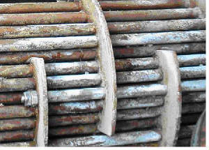
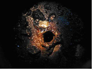
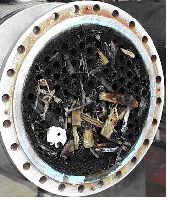
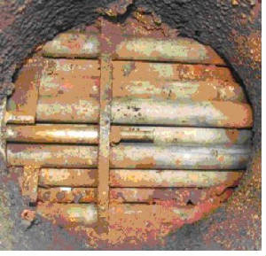
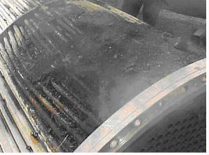
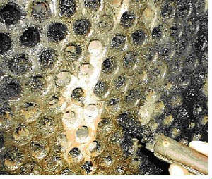
Fouling The deposition of any undesired material on heat transfer surfaces is called fouling.  Fouling may significantly impact the thermal and mechanical performance of heat exchangers.  Fouling is a dynamic phenomenon which changes with time.
Fouling increases the overall thermal resistance and lowers the overall heat transfer coefficient of heat exchangers.  Fouling also impedes fluid flow, accelerates corrosion and increases pressure drop across heat exchangers.
Different types of fouling mechanisms have been identified.  They can occur individually but often occur simultaneously.  Descriptions of the most common fouling mechanisms are provided below:

Scaling/Crystallization Fouling:
Scaling is the most common type of fouling and is commonly associated with inverse solubility salts such as calcium carbonate (CaCO3) found in water.  Reverse solubility salts become less solute as the temperature increases and thus deposit on the heat exchanger surface.  Scale is difficult to remove mechanically and chemical cleaning may be required. 
scale formation fouling
Particulate/Sedimentation Fouling:
Sedimentation occurs when particles (e.g. dirt, sand or rust) in the solution settle and deposit on the heat transfer surface.  Like scale, these deposits may be difficult to remove mechanically depending on their nature. 
rust fouling
debris fouling
Corrosion Fouling:
Results from a chemical reaction which involves the heat exchanger surface material.  Many metals such as copper and aluminum form adherent oxide coatings which serve to passivate the surface and prevent further corrosion.  Metal oxides which are corrosion products exhibit quite a low thermal conductivity and even relatively thin coatings of oxides may significantly affect heat exchanger performance.
corrosion fouling
Chemical Fouling:
Fouling from chemical reactions in the fluid stream which result in the deposition of material on the heat exchanger surface.  This type of fouling is common for chemically sensitive materials when the fluid is heated to temperatures near its decomposition (degradation) temperature.  Coking of hydrocarbon material on the heat transfer surface is also a common chemical fouling problem. 
chemical reaction fouling
chemical polymerization fouling
Freezing Fouling:
Occurs when a portion of the hot stream is cooled to near the freezing point of one of its components.  An example in refineries is when paraffin solidifies from a cooled petroleum product.  Another example is freezing of polymer products on the heat exchanger surface. 
freeze fouling
Biological Fouling:
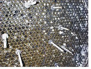
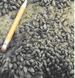
Occurs when biological organisms grow on heat transfer surfaces.  It is a common fouling mechanism where untreated water is used as the coolant.  Problems range from algae to other microbes such as barnacles and zebra mussels.  During seasons when these microbes are said to bloom, colonies several millimeters deep may grow across the surface within hours, impeding circulation near the surface wall and impacting heat transfer.   
biological fouling
    
It is important to consider fouling in the design of a heat exchanger.  There are different methods to provide the added heat transfer area needed to account for the expected fouling and maximize runtime between cleaning.  For shell and tube heat exchanger, the common method is to use fouling factors.  For other types of heat exchangers, excess heat transfer area is often used.  However, fouling is a self-fulfilling prophecy and the selection of fouling factors or excess area must be done carefully.
Fouling tendencies depends on the type of heat exchanger and the fluids.  During the design stage certain considerations may help minimize fouling experienced in the field:
  • If possible, allocate the more fouling fluid to the tube side
  • Design for a fouling fluid velocity of 5 ft/sec on the tube side and 3 ft/sec on the shell side
  • Try to keep the fluid velocity constant
  • Allow for easy access for cleaning
  • In water service, ensure the tube wall temperature is not too high to create salt deposits or render treatment chemicals ineffective
  • Do not throttle water flows in winter time

Fouling Factors

$
0
0
Fouling Factors 
The use of fouling factors is a common method to account for the expected fouling tendency of a process and maximize the runtime between cleaning for shell and tube heat exchangers.  Fouling factors are selected to represents the fouling expected just before cleaning time.  This method results in the heat exchanger performing better when clean and just meeting the heat transfer requirements when fouled. 
Both physical and economical considerations must be reviewed when selecting the appropriate fouling factors.  Physical considerations that influence the selection of the fouling factors are:
  • nature of fluid
  • type of fouling
  • fluid temperature
  • wall temperature
  • material of construction
  • fluid velocity
Economic considerations that influence the fouling factors selection are:
  • Initial purchase cost of the exchanger
  • Variations of cost with size
  • Frequency of cleaning required
  • Cost of cleaning (including loss of production)
  • Fluid pumping cost
  • Desired net return on investment
    
The initial purchase cost increases with increasing fouling resistance while cleaning and down-time expenses generally decrease with increasing fouling resistance.  However, using large fouling factors can lead to more fouling than anticipated and result in more frequent cleaning.  Selecting the optimum fouling factors involves satisfying conflicting goals.

Fouling Factors Fouling is a function of the system and the equipment used.

$
0
0
Fouling Factors
Fouling is a function of the system and the equipment used.  Parameters which influence the fouling rate in a system include: the type of fluid, the type of heat exchanger, the temperatures, the velocities and the materials of construction.  The actual fouling rate is different for each application. 
There are numerous resources for fouling factor values.  The best source is from existing operating facilities.  When production data is available, it can be used to calculate the actual fouling factors for the system.  Together with the maintenance and cleaning history, this provides the best resource for selecting the fouling factors for a particular application.
However, when production data is not available, one must rely on other sources.  Over the years, typical fouling factors have been compiled for various systems and fluids.  The tables below show some of these typical fouling factors:
Process Fluids
Fouling Resistance
 
(ft2-°F-hr/BTU)
Oils
         Fuel Oil #2
0.002
         Fuel Oil #6
0.005
         Transformer Oil
0.001
         Engine Lube Oil
0.001
  
Gases and Vapors
         Acid gas
0.002 - 0.003
         Ammonia vapor
0.001
         Chlorinated hydrocarbons vapors
0.001 - 0.0015
         Chlorine Vapor 
0.002
         CO2 vapor
0.001
         Compressed Air
0.001
         Hydrogen
0.0005
         Hydrogen (saturated with water)
0.002
         Light Hydrocarbon vapors (clean)
0.001
         Natural Gas
0.001 - 0.002
         Natural Gas Flue Gas
0.005
         Nitrogen
0.0005
         Polymerizable vapors (with inhibitor)
0.003 - 0.03
         Refrigerant Vapors (oil bearing)
0.002
         Solvent Vapor
0.001
         Stable Overhead Products
0.001
         Steam (non-oil bearing)
0.0005
         Steam (exhaust, oil bearing)
0.0015 - 0.002
  
Liquids
         Ammonia Liquid
0.001
         Ammonia Liquid (oil bearing)
0.003
         CO2 Liquid
0.001
         Chlorinated hydrocarbons liquid
0.001 - 0.002
         Chlorine Liquid
0.002
         DEG & TEG Solutions
0.002
         Ethylene Glycol Solutions
0.002
         Gasoline
0.002
         Heavy Fuel Oils
0.005 - 0.007
         Heavy Gas Oil
0.003 - 0.005
         Hydraulic Fluid
0.001
         Kerosene
0.002 - 0.003
         Light Gas Oil
0.002 - 0.003
         Light hydrocarbon liquid (clean)
0.001
         MEA & DEA Solutions
0.002
         Naphtha and Light Distillates
0.002 - 0.003
         Organic Heat Transfer Liquids
0.002
         Refrigerant Liquids
0.001
                                                       
Water
Fouling Resistance
Fouling Resistance
 
(ft2-°F-hr/BTU)
(ft2-°F-hr/BTU)
water temperature
 125°F or less
over 125°F
water velocity
3 ft/s or less
over 3 ft/s
3 ft/s or less
over 3 ft/s
     
Boiler Blowdown Water
0.002
0.002
0.002
0.002
Brackish Water
0.002
0.001
0.003
0.002
Condensate
0.0005
0.0005
0.0005
0.0005
Cooling Tower Water (treated)
0.001
0.001
0.002
0.002
Cooling Tower Water (untreated)
0.003
0.003
0.005
0.004
City or Well Water
0.001
0.001
0.002
0.002
River Water (minimum)
0.002
0.001
0.003
0.002
River Water (average)
0.003
0.002
0.004
0.003
River Water (muddy or silty)
0.003
0.002
0.004
0.003
Sea Water
0.0005
0.0005
0.001
0.001
Treated Boiler Feed Water
0.001
0.0005
0.001
0.001
 

A recent United Nations Environment Program (UNEP) report makes three key findings:

$
0
0
A recent United Nations Environment Program (UNEP) report makes three key findings:
That going green "not only generates increases in wealth, in particular a gain in ecological commons or natural capital, but also (over a period of six years) produces a higher rate of GDP growth";
That there is "an inextricable link between poverty eradication and better maintenance and conservation of the ecological commons, arising from the benefit flows from natural capital that are received directly by the poor";
That "in the transition to a green economy, new jobs are created, which in time exceed the losses in "brown economy" jobs.
Economic Opportunity
Treating the environment as an externality may generate short-term profit at the expense of sustainability. Sustainable business practices, on the other hand, integrate ecological concerns with social and economic ones (i.e., the triple bottom line). Growth that depletes ecosystem services is sometimes termed "uneconomic growth" as it leads to a decline in quality of life. Minimizing such growth can provide opportunities for local businesses. For example, industrial waste can be treated as an "economic resource in the wrong place". The benefits of waste reduction include savings from disposal costs, fewer environmental penalties, and reduced liability insurance. This may lead to increased market share due to an improved public image. Energy efficiency can also increase profits by reducing costs.
Sustainability Principles
1. Reduce dependence upon fossil fuels, underground metals, and minerals;
2. Reduce dependence upon synthetic chemicals and other unnatural substances;
3. Reduce encroachment upon nature;
4. Meet human needs fairly and efficiently.

Uttarakhand havoc not due to cloudburst: Experts Intense rains in Kedarnath-Badrinath unleashed death and destruction

$
0
0

Facing criticism that it didn't predict the cloudburst that ravaged Uttarakhand, the Indian Meteorological Department (IMD) said on Wednesday that cloudburst was not to blame for the disaster that has killed hundreds.
Rather, it were the intense rains in the Kedarnath-Badrinath sector that unleashed the death and destruction.
"Uttarakhand didn't get hit by a cloudburst. It were the intense rains," Manmohan Singh, director of the meteorological office in Shimla, told IANS.
Explaining the reasons for the deluge in Kedarnath-Badrinath mountains, he said landslides were caused by heavy rains, caused by the clouds from the Bay of Bengal.
A simultaneous tropical storm system generating over the Mediterranean escalated the rains.
"Thus, clouds from both the east and west gathered over the Kedarnath-Badrinath area and caused heavy rains. These triggered landslides and the havoc," he said.
Hundreds have died in the natural calamity since June 15. Thousands of others have been hit, and many are still stranded in remote hills.
According to meteorological terminology, a "cloudburst" occurs when a cloud empties out its water content at speeds of over 10 cm per hour for more than an hour at one place.
When this happens, the clouds are at an altitude of 12-13 km.
According to the Met office in Dehradun, the rainfall figures of June 14-17 in Uttarakhand showed that it was a gradual build-up.
On June 14, Dehradun had a rainfall of only 5 cm and Tehri 3 cm.
On June 15, the figures jumped to 22 cm in Dehradun, at Purola 17 cm, at Devprayag 13 cm, at Uttarkashi 13 cm and at Tehri 12 cm.
However, the next day rainfall was 37 cm in Dehradun, 24 cm in Mukteshwar, 22 cm Haridwar and 21 cm in Uttarkashi.
It was 18 cm in Mukteshwar, 22 cm in Champawat, 28 cm in Haldwani, 17 cm in Nainital and 12 cm in Ranikhet on June 17.
"The pattern of rain shows a sudden rise and heavy rainfall over the four days," an IMD official in Dehradun said.
"It also shows that the heavy rain covered a larger area over the four days, creating a catastrophe at Kedarnath, Badrinath, Joshimath and other nearby areas," the official said.
Moreover, the cloudburst is highly a localised phenomena and a freak disaster. It takes place at the foot of the typically steep hills and it recurs at a particular place, he said.
Uttarakhand Chief Minister Vijay Bahuguna has blamed the IMD for lack of warning on cloudburst.
"The IMD warning was not clear enough. It only said there would heavy rains and snowfall in the upper ridges. We were not warned about any cloudburst," Bahuguna told a news channel.

WISHING A VERY HAPPY BIRTHDAY TO SHRI K.S. RAJU SIR EHSQ BLOG DEDICATED TO NAGARJUNA GROUP

$
0
0
 TOTAL NO. OF POST

 https://www.youtube.com/watch?v=uA01ad1V9X4

About me

GenderMale
IndustryManufacturing
OccupationEHSQ
LocationKAKINADA,ANDHRA PRADESH,India
IntroductionM.Sc., PGDEPL,CES,DCA, Ph.D ENVIRONMENMENTAL SCIENCE & LAW, EX IIM LUCKNOW FELLOW, EX IGIDR MUMBAI FELLOW, EX PRESIDENT-EPSA, ISCN, TGTF, WORKING at NAGARJUNGA GROUP-NFCL
TOP ARTICLES
387
376
346
334
25 Jan 2013                                                                                               
325

 PAGE VIEWS HISTORY
Pageviews yesterday
796
Pageviews last month
26,197
Pageviews all time history
247,159
 TOP TEN COUNTIRES VIEWS EHSQ BLOG
United States
137216
India
42418
United Kingdom
4785
South Korea
3838
France
2409
Germany
2018
Russia
1995
Canada
1734
Philippines
1452
Malaysia
1422

Delhi air pollution lessons for other metros

$
0
0

Delhi air pollution lessons for other metros

New Delhi, Dec. 17: Air pollution over Delhi kills at least 20 people every day and triggers an estimated six million asthma attacks each year, a study has suggested.
Researchers at IIT Delhi say their study of the capital’s air pollution loads also holds lessons for India’s other metros on why efforts to improve city air quality sometimes don’t work.
The study, published last week in the journal Environmental Development, used a mathematical model to estimate the health impacts of air pollution from sources such as vehicle exhaust, diesel generators and brick kilns.
Using the concentrations of air pollutants observed over the city during 2010, the study estimated that air pollution contributes to anything from 7,350 to 16,200 premature deaths each year. (See chart)
Government air pollution readings show that the average levels of pollutant particles less than 10 micrometres in size (PM10) over Delhi increased two-and-a-half-fold to 260 micrograms per cubic metre between 2001 and 2010. This average value is four times the level prescribed under national standards and 13 times the level stipulated by the World Health Organisation.
The IIT Delhi study suggests that reducing pollution from a single source will not pull down PM10 concentrations to levels below the standard limit of 60 micrograms per cubic metre.
“A single clean-up strategy won’t work — that’s a lesson for other metros,” said Sarath Guttikunda, a project scientist at the Transport Research and Injury Prevention Programme at IIT Delhi and the study’s principal investigator.
A decade ago, the Delhi government initiated a diesel-to-CNG conversion plan but, Guttikunda said, the focus was almost entirely on public transport. “But diesel-burning continues for things other than buses. And there are many other sources of pollution,” Guttikunda said.
Guttikunda and co-author Rahul Goel, a PhD research scholar at IIT Delhi, have generated an emissions inventory that quantifies air pollution from vehicles as well as diesel generator sets, power plants, road dust, industries and the burning of city waste.
The study suggests that emissions from vehicles account for about 13 per cent of the PM10, 53 per cent of the oxides of nitrogen, 51 per cent of the volatile organic compounds and 18 per cent of the carbon monoxide in the air.
Diesel generator sets contribute 4 per cent of the PM10, 25 per cent of the oxides of nitrogen, 14 per cent of the volatile organic compounds, and 7 per cent of the carbon monoxide.
Guttikunda and Goel estimated the health impacts through a model that computes mortality and illness at different levels of concentrations of air pollutants.
Delhi is also girdled by hundreds of brick kilns that feed the construction industry across the National Capital Region. The study has estimated that brick kilns release 11 per cent of the PM10 and 12 per cent of the carbon monoxide.
The city’s colossal waste is another source of air pollution. Delhi’s three active landfills have a combined capacity of 5,000 tonnes of garbage per day, but the city churns out 9,000 tonnes a day. A part of the garbage is burned at landfill sites and elsewhere, and accounts for 7 per cent of the PM10.
“These findings highlight the importance of examining pollution sources beyond traffic emissions,” said Bhola Ram Gurjar, associate professor of civil engineering at IIT Roorkee, who was not associated with this study.
“What the trends in Delhi tell us is that multiple strategies are needed to address air pollution,” Guttikunda said. The researchers have called for a combination of measures that include technology and behavioural interventions.
Viewing all 8077 articles
Browse latest View live